
Open vSwitch gave us a programmable dataplane. Open Virtual Network added a control plane. Together they power Neutron in most OpenStack clouds. This tutorial explains the architecture, compares OVS vs. OVN, and shows how to trace a packet from instance to instance in OpenStack.
You’ve deployed two instances on different compute nodes. Same tenant. Same network. They can’t ping each other. Security groups allow ICMP. The physical network is up. Sound familiar? In OpenStack Neutron with OVN, most cross-host packet losses are not bugs – they are logical flow denials waiting to be read.
When your OpenStack instances can ping each other on the same compute node but go silent across hypervisors, you’re dealing with a networking failure that spans two layers: the dataplane and the control plane. Understanding how OVS and OVN operate across those layers turns a frustrating mystery into a solvable problem — because that’s where most OpenStack networking issues actually hide.
What is SDN? (Software-Defined Networking)
Before we dive into OVS and OVN, it helps to understand why these technologies exist in the first place.
Traditional networking works like this: each switch and router has its own control plane deciding where packets go and data plane forwarding packets. To change how traffic flows, you reconfigure each device individually – often by using protocols like NETCONF or RESTCONF. This approach works until you need to scale. In a cloud environment with hundreds of hypervisors and thousands of VMs, manual per-device configuration becomes impossible.
Software-Defined Networking (SDN) changes the game by separating the control plane from the data plane. A central SDN controller decides where traffic should go, and the underlying switches and routers simply follow those instructions. This separation brings three major benefits to cloud environments:
| Benefit | Why it matters in cloud environments |
| Centralized control | You manage network policy centrally, not per-switch |
| Programmability | Networks adapt dynamically as VMs are created, migrated, or deleted |
| Automation | No manual switch configuration |
OVS and OVN are SDN technologies. OVS provides the high-performance data plane on each hypervisor. OVN provides the distributed control plane that tells OVS what to do. Together, they implement SDN for OpenStack Neutron.
What is Open vSwitch?
Open vSwitch (OVS) is an open source virtual switch that speaks OpenFlow, supports tunnel encapsulation (VXLAN, GRE, Geneve), and integrates with KVM, Xen, and other virtualization platforms. Unlike basic Linux bridges, OVS was built for large data center environments: it handles high throughput via a kernel module, gives you visibility with sFlow/NetFlow, and lets you apply QoS per flow.
OVS became the default switch for OpenStack Neutron back in 2012. But it had a limitation: it exposed low-level OpenFlow rules, not logical network abstractions like “virtual router” or “security group”. Managing OVS directly at scale meant writing complex flows via CLI as Neutron OVS Agent did back in the days. And that was the point where OVN came in.
OVN – The Control Plane OVS was Missing
Open Virtual Network (OVN) started as part of the OVS project in 2013 and reached maturity by 2016. OVN does not replace OVS. It sits on top of it, providing a logical networking model – virtual switches, routers, ports and ACLs that are translated automatically into OpenFlow rules inside OVS.
Think of it this way:
- OVS = the worker who moves packets
- OVN = the manager who decides where packets should go and remembers the network topology
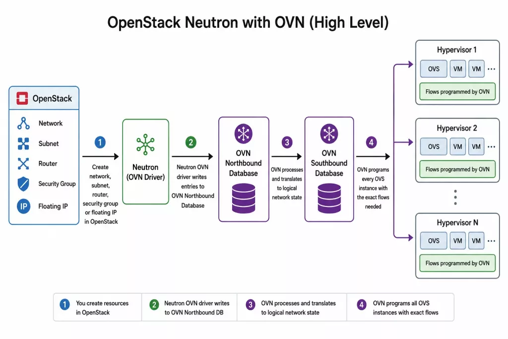
Today, OVN is the default Neutron driver in most OpenStack distributions. When you create a network, subnet, router, or security group in OpenStack, Neutron calls the OVN driver. That driver writes entries into OVN’s Southbound Database. OVN then programs every OVS instance on every hypervisor with the required flows.
OVS vs. OVN – Comparison Table
| Aspect | OVS alone | OVS + OVN |
| Control plane | None (you configure flows manually or via OpenFlow controller) | Built-in distributed control plane |
| Logical abstractions | No – you work with ports, flows, tunnels | Yes – logical switches, routers, ports, ACLs |
| OpenStack integration | Mapping from Neutron to OVS flows | Native driver (Neutron ML2/OVN) with automation |
| Scalability | Flow table explosion in large environments | Southbound DB aggregates topology allowing larger scale |
| Typical use case | Standalone SDN dataplane or simple labs, old releases of OpenStack, Proxmox | OpenStack from Ussuri release, Kubernetes (OVN-K8s) |
| Learning curve | Low for basic switching, steep for OpenFlow | Moderate – you think in logical networks, not flows |
Bottom line: OVS standalone can be used for small labs or test setups. OVN is what makes automated networking work at a cloud scale.
Why ML2/OVN Became the Standard
For many years, ML2/OVS was the most widely used OpenStack Neutron backend. In this architecture, Open vSwitch (OVS) handled packet forwarding, while Neutron agents provided services such as routing and DHCP. This approach introduced additional agents to manage, showed scaling limitations and had the infamous full-sync issue which could bring Neutron database or RabbitMQ down when too many neutron-openvswitch-agents were restarted at once.
OVN was designed to simplify OpenStack networking by integrating networking functions into a distributed SDN architecture. Instead of relying on multiple Neutron agents, OVN provides native support for routing, DHCP, and network policy management through a centralized control plane and distributed data plane.
The main advantages of ML2/OVN include:
- Fewer agents to manage
- Better scalability for large cloud environments
- Native distributed routing and DHCP services
- Simpler operations and troubleshooting
As OVN matured, it became the primary focus of networking development within the OpenStack community. By 2023.1 (Antelope) release ML2/OVN became the default solution in most OpenStack deployment tools and vendor solutions reflecting the broader shift toward OVN as the preferred backend.
For all new OpenStack deployments, ML2/OVN is the recommended choice and is considered the standard approach for modern OpenStack networking. Older deployments still using ML2/OVS are encouraged to migrate to ML2/OVN.
OVN Architecture Overview
At a high level, OVN separates responsibilities into two distinct layers:
- Control plane
- Data plane
The control plane is responsible for defining how the virtual network topology should look like. And the data plane is responsible for actually forwarding packets according to the topology and instructions.
This separation allows OVN to maintain a consistent network model while distributing packet processing across the infrastructure.
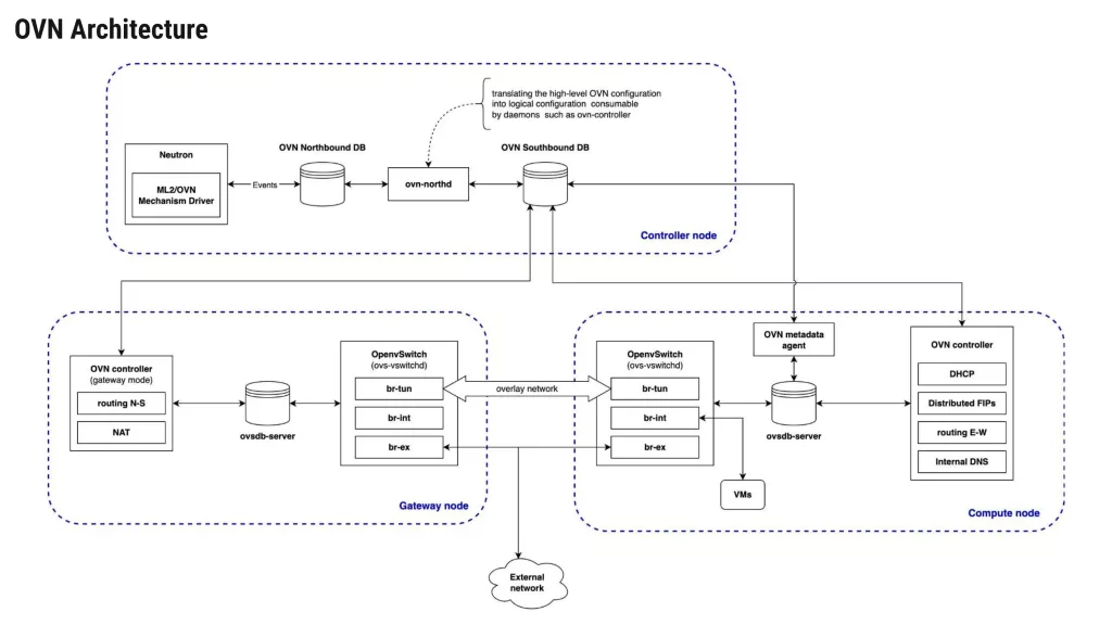
Control Plane Components
At the top of the architecture sits OpenStack Neutron.
When users create Networks, Routers, Subnets, Security groups, or Floating IPs through OpenStack APIs, Neutron passes this information to the ML2/OVN mechanism driver.
The mechanism driver converts OpenStack networking objects into OVN logical entities and stores them inside the OVN Northbound Database (NBDB).
The Northbound Database represents the desired state of the network. It answers the question: “What should the virtual network look like?”
When OpenStack users create networking resources, the ML2/OVN driver converts those resources into OVN logical objects and stores them in the Northbound Database.
Examples include:
- Logical switches
- Logical routers
- ACLs
- NAT policies
- Load balancers
- Logical ports
The ovn-northd is the central control daemon of OVN. It acts as a translator between the Northbound and Southbound databases.
Its responsibility is to:
- Read logical network definitions from the Northbound Database.
- Convert them into implementation details.
- Populate the Southbound Database.
Whenever a network change occurs, ovn-northd recalculates the required network behavior and distributes updated information throughout the environment.
Data Plane Components
The Southbound Database (SBDB) acts as the communication layer between OVN’s control plane and the individual hosts running workloads. It answers the question: “How should each node implement the desired network state?”
It contains implementation-specific information such as:
- Chassis registrations
- Tunnel endpoints
- Datapath bindings
- Port bindings
- Flow information
Each compute node and gateway node runs:
- Open vSwitch
- OVSDB
- ovn-controller
The ovn-controller process continuously monitors the Southbound Database and retrieves configuration relevant to its local chassis (compute or gateway node).
It then programs Open vSwitch accordingly by creating:
- Tunnel configurations
- Datapath entries
- Logical flows
- OpenFlow rules
This enables each node to enforce networking behavior independently while remaining synchronized with the cluster.
| Overview of Components:Northbound Database (NB DB) Stores the logical network configuration as intended by the administrator or OpenStack. Example entries: logical switches, routers, ports, ACL rules. Neutron writes directly to the NB DB via the OVN driver.Southbound Database (SB DB) Stores the actual, low-level state calculated from the NB DB. Each chassis (OVS on hypervisor) reports its local OVS port bindings here. The SB DB also holds logical flow tables – a mid-level representation between Neutron’s intent and OVS’s OpenFlow rules.ovn‑controller Runs on every compute node. It watches the SB DB, translates logical flows into OpenFlow flows, and pushes them into the local br-int integration bridge. It also reports back local port status and tunnel endpoint IPs.ovn‑northd Runs on a centralized controller node. Its job is to translate the Neutron-configured NB DB into the more detailed, distributed-ready SB DB. It runs continuously, watching for changes and updating the SB DB accordingly.Tunnel overlay OVN uses tunnels (Geneve or VXLAN) to carry traffic between compute nodes. Each OVN chassis has a tunnel endpoint IP. When a packet leaves a VM, OVN encapsulates it and sends it to the destination chassis, where decapsulation happens before delivery. Tunnel overlays work over both L2 and L3 networks allowing greater cloud scalability. |
Understanding the OVN Workflow
The complete workflow is essentially a seven-step process:
- User creates a network resource in OpenStack.
- Neutron writes the logical configuration to the Northbound Database.
- ovn-northd converts logical intent into implementation details.
- That information is written into the Southbound Database.
- Local ovn-controller processes receive updates.
- Open vSwitch is (re-)programmed automatically.
- Traffic begins flowing according to the new desired configuration.
This process occurs continuously and transparently, allowing operators to manage networking through OpenStack APIs while OVN handles the underlying implementation.
East-West vs. North-South Traffic in OVN
Before we dive into logical flows and packet tracing, it helps to understand two traffic patterns that OVN handles very differently.
East-West traffic refers to communication between workloads inside the same data center or cloud environment. In OpenStack terms, this means:
- VM-to-VM within the same tenant network
- VM-to-VM across different tenant networks (routed via a virtual router)
- Traffic between VMs and container workloads
East-West traffic typically stays inside the OVN overlay network. It is encapsulated in tunnels (Geneve/VXLAN) and never touches the physical gateway unless routed over L3 provider networks. This communication pattern can be commonly observed in modern software architectures, where backend operations, database replication, and internal API calls are done in private, isolated tenant networks.
North-South traffic refers to communication between workloads and the outside world. Examples include:
- A user accessing a web server running on an OpenStack instance via a floating IP
- An instance downloading packages from the Internet
- User connecting to the cloud environment via a VPN
North-South traffic must exit the OVN overlay and reach the physical network. In OpenStack Neutron, this typically happens through:
- Virtual routers with gateway ports attached to a provider network
- Floating IPs – which use NAT (DNAT) to map a public IP to a private instance IP
- Load balancers or virtual gateways (e.g., OVN’s own distributed gateway ports)
OVN Trace Tool – Debugging Traffic End-to-End
Now that we understand the conceptual path of a packet traveling from a VM to its destination — whether that destination is on the same logical switch, a different tenant network, or the internet. ovn-trace is the tool that lets you verify this path in practice.
Rather than sending real packets and observing what happens, ovn-trace simulates the packet’s journey through OVN’s logical pipelines. It shows you, step by step, which logical flows match, what actions are taken, and where the packet would exit or be dropped.
Some administrators avoid ovn-trace because the output appears complex at first. However, once you understand the pipeline stages, it becomes as readable as tcpdump or tracepath — and far more revealing, because it shows OVN’s internal decision-making, not just network-level behavior.
When the Pipeline Behavior Changes
When you run ovn-trace, the packet’s path through the pipeline depends entirely on its destination. OVN applies different logical pipeline stages based on where the traffic is headed:
- Destination inside the same logical switch (same Neutron network)
The packet undergoes L2 switching only. The pipeline applies security group ACLs (ingress and egress), performs MAC learning and lookup, and forwards the packet directly to the destination port. No routing or NAT occurs. - Destination in a different logical switch but within the same tenant (requires a logical router)
The packet passes through the logical switch ingress pipeline, then enters the logical router pipeline. Here, OVN performs:- TTL decrement
- Route lookup
- MAC address rewriting
- Egress pipeline on the destination logical switch
- No NAT is applied unless the destination is on a different tenant network that requires floating IPs.
- Destination outside the cloud entirely (external internet or provider network)
The packet goes through:- Logical switch ingress
- Logical router pipeline (route lookup)
- SNAT/DNAT (if the source VM has a Floating IP or the router has SNAT enabled)
- Gateway chassis selection (or local routing when DVR is enabled)
- localnet port pipeline to egress to the physical network via br-ex
This distinction is critical because a misconfiguration that breaks external connectivity (e.g., missing SNAT) won’t affect internal east-west traffic. ovn-trace makes this clear by showing you exactly which pipeline stages are traversed and where the packet stops.
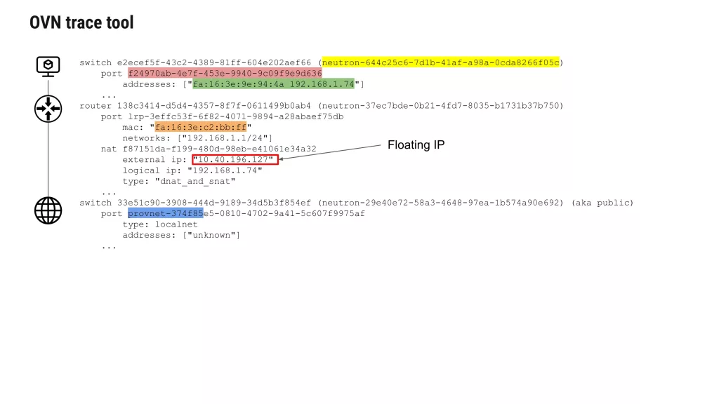
Example Trace: Unicast TCP Traffic to the Internet
In the example below, we trace traffic originating from a VM on the private network:
- Source port: from VM’s logical port f24970ab…
- Source MAC/IP: fa:16:3e:9e:94:4a / 192.168.1.74
- Destination: public IP 8.8.8.8
- Protocol: TCP, destination port 80
The trace command:
The output shows each stage:
ovn-trace --ct=new --summary neutron-644c25c6-7d1b-41af-a98a-0cda8266f05c \
'inport == "f24970ab-4e7f-453e-9940-9c09f9e9d636" && \
eth.src == fa:16:3e:9e:94:4a && ip4.src == 192.168.1.74 && \
eth.dst == fa:16:3e:c2:bb:ff && ip4.dst == 8.8.8.8 && \
ip.ttl == 64 && ip4 && tcp.dst == 80 && tcp.src == 3000'
- Packet enters the logical switch from the VM port.
- Ingress ACLs (security groups) are evaluated.
- Packet is forwarded to the logical router port.
- Logical router pipeline: TTL decremented, route lookup finds the default route.
- NAT rule is applied (dnat_and_snat):
logical ip: 192.168.1.74
external ip: 10.40.196.127
type: dnat_and_snat
- Packet is forwarded to the localnet port on the provider network.
- Egress ACLs are evaluated.
- Packet exits via the provnet-374f85… port, which maps to physical bridge br-ex.
The trace output shows exactly this progression, confirming that NAT and routing are working as expected.
Adjusting Verbosity
You can control how much detail the trace shows:
ovn-trace --summary ... # High-level stages onlyovn-trace --minimal ... # Minimal output (just the result)ovn-trace --detailed ... # Full pipeline with all matches and actions
When to Use ovn-trace
Use ovn-trace when:
- A VM cannot reach a specific destination, but other VMs on the same network can.
- You suspect a NAT or routing misconfiguration.
- You want to confirm which gateway chassis is handling a particular flow.
- Security group ACLs appear to be dropping traffic.
- You need to verify that a change (e.g., adding a Floating IP) has been applied correctly in the OVN pipeline.
What ovn-trace Cannot Do
- It does not send real packets, so it cannot detect physical network issues (e.g., cable failures, switch misconfiguration).
- It does not test actual performance or latency.
- It relies on the current state of the OVN databases — if the databases are out of sync, the trace reflects that incorrect state.
Despite these limitations, ovn-trace is one of the most valuable debugging tools in the OVN ecosystem. Once you become comfortable with its output, troubleshooting becomes a matter of reading the pipeline rather than guessing at the problem.
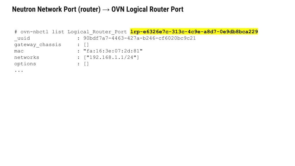
Understanding Neutron to OVN Mapping
Before diving into specific resource mappings, it is helpful to understand a fundamental principle: almost every Neutron object has a direct counterpart in OVN. This one-to-one correspondence is what makes OVN debugging systematic rather than opaque.
When you create a network, subnet, port, router, or security group in OpenStack, the ML2/OVN mechanism driver translates that API request into entries in the OVN Northbound Database. The ovn-northd daemon then converts those logical entries into flow instructions in the Southbound Database, which are finally pushed to ovn-controller on each compute and gateway node.
The following sections show the exact mapping for each Neutron resource type — including the specific ovn-nbctl and ovn-sbctl commands you can use to verify that Neutron’s configuration has propagated correctly into OVN.
Logical Flows vs. Physical Flows
One of the most valuable concepts in OVN is the separation between logical flows and physical flows.
Logical flows operate at the level of your virtual network topology. They reference objects like logical switches, logical routers, and logical ports. A logical flow might say: “Packets from logical port A to logical port B on the same logical switch are allowed.” You don’t need to deal with physical interfaces, tunnel IPs, or MAC addresses here.
Physical flows (OpenFlow rules) exist inside OVS on each hypervisor. They reference physical ports like eth0, tap devices, tunnel interfaces, and exact match fields like VLAN tags or tunnel keys. These flows are generated automatically by ovn-controller based on the logical flows.
Why does this matter? When troubleshooting, you might run ovn-sbctl lflow-list, which shows you logical flows – the intent. When you run ovs-ofctl dump-flows br-int, you are looking at physical flows – the actual forwarding rules installed in the kernel. A mismatch between the two is often the root cause of connectivity issues.
Key OVN CLI Tools for Troubleshooting
Before we move on to the troubleshooting guide, here are some essential OVN commands you will use:
| Command | Purpose |
| ovn-sbctl show | Display chassis and port bindings |
| ovn-sbctl lflow-list | List all logical flows in the SB DB |
| ovn-sbctl dump-flows | Show OpenFlow flows generated by OVN (alternative view) |
| ovn-trace (or ovn-sbctl lflow-trace) | Simulate a packet path through logical flows |
| ovn-nbctl show | Display logical network topology (switches, routers, ports) |
| ovs-ofctl dump-flows br-int | Show physical OpenFlow rules on a compute node |
Logical Networking Concepts
As already outlined, OVN introduces several abstractions that simplify network management. Let’s have a closer look at those.
Logical Switches
Logical switches provide Layer 2 connectivity between workloads.
Unlike physical switches, they exist entirely in software and can span multiple hosts.
A logical switch can connect virtual machines regardless of where they are physically located in the data center.
Logical Routers
Logical routers provide Layer 3 connectivity between logical networks.
These routers support:
- Static routing
- Distributed routing
- NAT
- External connectivity
Unlike traditional centralized routers, OVN routers can distribute routing functionality throughout the environment for high availability.
Logical Ports
Logical ports represent attachment points between workloads and logical networks. Every virtual machine interface is typically associated with a logical port.
OVN uses these ports to determine where traffic should enter and exit the logical topology.
Access Control Lists (ACLs)
ACLs define security policies governing traffic between workloads. Examples include:
- Allowing SSH access
- Allowing access only to certain ports (e.g. 443)
- Enforcing tenant isolation
OVN translates these logical policies into dataplane enforcement rules automatically.
Network Address Translation (NAT)
OVN supports multiple forms of NAT including:
- Source NAT (SNAT)
- Destination NAT (DNAT)
- Floating IP mappings
NAT policies are associated with logical routers and distributed throughout the environment.
Following a Packet Through OVN
One of the best ways to understand OVN is to trace a packet’s journey from a virtual machine to its destination — whether that destination is another VM on the same compute node, a VM on a different node, or an external server on the internet.
This section walks through each logical stage of the packet’s path. Later, we will show how to verify this behavior using the ovn-trace debugging tool.
Stage 1: Packet Leaves the Source VM
A VM sends a packet from its virtual network interface. The hypervisor passes this packet to the OVS bridge br-int (the integration bridge) on the compute node where the VM resides.
The VM has no knowledge of OVN — it simply sees a standard Ethernet interface with a MAC address, IP address, and default gateway. In our example:
- VM MAC: fa:16:3e:9e:94:4a
- VM IP: 192.168.1.74
- Default gateway: 192.168.1.1 (the logical router interface)
Stage 2: Packet Enters the Logical Switch
The ovn-controller on the compute node has already programmed OpenFlow rules into br-int based on the OVN Southbound database. These rules direct packets to the correct logical switch.
Each Neutron network corresponds to an OVN logical switch. When the packet arrives, OVN identifies which logical switch port it came from by matching the inbound interface.
To see the logical switch and its ports:
ovn-nbctl show neutron-<NETWORK_UUID>
For a VM port, the output shows an empty type (“”), confirming it is a regular compute port:
port f24970ab-4e7f-453e-9940-9c09f9e9d636 addresses: ["fa:16:3e:9e:94:4a 192.168.1.74"] type: ""
Stage 3: Layer 2 Resolution (ARP/ND)
If the packet’s destination is on the same logical switch (same Neutron network), OVN performs layer 2 forwarding:
- The packet’s destination MAC is looked up in OVN’s logical switch MAC binding table.
- OVN determines which logical switch port has that MAC address.
- If the destination is on a different compute node, OVN encapsulates the packet in a tunnel (VXLAN or Geneve) and forwards it to the correct hypervisor.
If the destination MAC is unknown (e.g., the VM is trying to reach a new IP), the VM first sends an ARP request (for IPv4) or an ND (for IPv6). OVN handles ARP natively without flooding the entire network — it responds locally if the IP belongs to a known port.
Stage 4: Packet Reaches the Logical Router (East-West Traffic)
When a VM sends a packet to an IP address on a different Neutron network that is connected via a shared logical router, the packet must pass through the logical router.
The VM sends the packet to its default gateway MAC address. OVN recognizes that this MAC belongs to a logical router port attached to the logical switch.
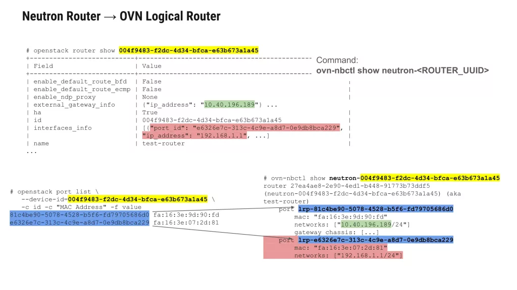
Inspect the logical router and its ports:
ovn-nbctl show neutron-<ROUTER_UUID>
Example output shows both internal and external ports:
router 81c4be90-5078-4528-b5f6-fd79705686d0 (test-router)
    port lrp-71a2b3c4-d5e6-4789-a0b1-c2d3e4f56789
        mac: "fa:16:3e:c2:bb:ff"
        networks: ["192.168.1.1/24"]
    port lrp-81c4be90-5078-4528-b5f6-fd79705686d0
        mac: "fa:16:3e:73:78:ee"
        networks: ["10.40.196.189/24"]
The internal router port (lrp-71a2b3c4…) is connected to the tenant network. Where an external router port (lrp-81c4be90…) connects to the provider network.
When the packet enters the logical router:
- OVN decrements the TTL.
- OVN looks up the destination IP in the router’s routing table.
- OVN rewrites the source MAC to the router’s egress port MAC and the destination MAC to the next hop’s MAC.
- The packet is forwarded to the logical switch attached to the destination network (for east-west traffic) or to the gateway chassis (for north-south traffic).
Stage 5: North-South Traffic and NAT
If the packet’s destination is outside the OpenStack cluster (e.g., 8.8.8.8), the logical router forwards it to a gateway chassis that has external connectivity.
For a VM with a Floating IP, OVN applies NAT rules. To view the NAT configuration you can run:
ovn-nbctl show neutron-<ROUTER_UUID>
Example NAT output:
nat dnat_and_snat external ip: "10.40.196.214" logical ip: "192.168.1.133" external mac: "fa:16:3e:4c:27:37" logical port: f24970ab-4e7f-453e-9940-9c09f9e9d636nat snat external ip: "10.40.196.141" logical ip: "192.168.1.0/24"
For a VM with a Floating IP, OVN performs:
- SNAT (Source NAT) — Rewrites the source IP from the VM’s fixed IP to the Floating IP (or gateway external IP) so return traffic can be routed back.
- DNAT (Destination NAT) — Rewrites the destination IP of incoming traffic from the Floating IP to the VM’s fixed IP.
In distributed mode (DVR enabled), the NAT happens on the compute node where the VM resides. In centralized mode, it happens on the dedicated gateway node.
To identify the active gateway chassis you need to run:
ovn-nbctl lrp-get-gateway-chassis <PORT_UUID>
ovn-sbctl get Chassis < CHASSIS_ UUID> host name
Stage 6: Egress to Physical Network
Once the packet has passed through the logical router and any NAT rules, it must leave the OVN overlay and enter the physical network.
This happens via a localnet port on the provider network’s logical switch. The localnet port is mapped to a physical bridge (typically br-ex) on the gateway chassis using bridge mappings.
Inspect the chassis bridge mappings:
ovn-sbctl get Chassis <CHASSIS_UUID> external_ids
Expected output:
{ovn-bridge-mappings="public:br-ex", ...}
Where public is the name of the provider network. The ovn-controller on the gateway chassis strips the OVN tunnel encapsulation (if any) and forwards the raw Ethernet frame onto br-ex, which then sends it out the physical NIC to the external network.
Stage 7: Return Path and Stateful Tracking
OVN maintains connection tracking (conntrack) for stateful services like NAT and security groups. When a response packet returns from the provider network:
- It enters via br-ex on the gateway chassis.
- OVN reverses the SNAT/DNAT translation using the connection tracking state.
- The packet is encapsulated and tunneled to the appropriate compute node.
- The compute node’s ovn-controller delivers the packet to the original VM.
For security groups, OVN uses ACLs attached to Port Groups. Each ACL rule is evaluated in the pipeline before forwarding decisions are made.
Verifying the Packet Path with ovn-trace
The conceptual path described above can be simulated using OVN’s built-in trace tool. For example, tracing TCP traffic from our VM to 8.8.8.8:
ovn-trace --ct=new --summary neutron-644c25c6-7d1b-41af-a98a-0cda8266f05c \
'inport == "f24970ab-4e7f-453e-9940-9c09f9e9d636" && \
eth.src == fa:16:3e:9e:94:4a && ip4.src == 192.168.1.74 && \
eth.dst == fa:16:3e:c2:bb:ff && ip4.dst == 8.8.8.8 && \
ip.ttl == 64 && ip4 && tcp.dst == 80 && tcp.src == 3000'
The output will show each pipeline stage: ingress from the logical switch, routing decision, NAT application, and egress to the provider network.
Summary of the Packet’s Journey
| Step | Location | Action |
| 1 | Source VM | Packet leaves VM’s virtual interface |
| 2 | br-int on compute | Packet enters OVN logical switch |
| 3 | Logical switch | Layer 2 forwarding or ARP resolution |
| 4 | Logical router | Routing, TTL decrement, MAC rewrite |
| 5 | Gateway chassis (or local compute with DVR) | SNAT/DNAT for Floating IPs |
| 6 | br-ex on gateway | Encapsulation stripped, egress to physical network |
| 7 | Return path | Connection tracking reverses NAT, tunnel back to compute |
Understanding this flow makes it much easier to diagnose where a packet might be dropped — whether at the logical switch level (port binding issues), the router level (missing routes or incorrect NAT), or the physical egress level (bridge mapping problems).
Final Thoughts
This guide has walked through OVN’s architecture, the Neutron-to-OVN mapping, packet flow mechanics, and practical troubleshooting scenarios. By now, the underlying pattern should be second nature:
Neutron API calls → OVN Northbound DB (logical intent and configuration)
ovn-northd → OVN Southbound DB (physical realization and binding)
ovn-controller on each hypervisor → OpenFlow rules in OVS (actual data plane enforcement)
This three-tier transformation is the heart of OVN’s power — and, occasionally, its complexity. When an OpenStack network isn’t working as expected, resist the urge to jump straight to packet captures. Instead, adopt a disciplined, top-down approach: start at the Southbound DB to see what OVN believes should be happening on the wire. Then verify the Northbound DB to confirm what Neutron originally requested. Compare the two. In most cases, the root cause lives in the gap between intent and realization — a duplicate chassis, stale binding, an unprocessed logical flow, or a misapplied ACL.
Beyond the core flow, remember to check the Chassis table for node liveness, the Binding table for port ownership, and the Logical_Flow table for pipeline ordering. Tools like ovn-trace are invaluable for simulating packet paths without touching production traffic, while the DB sync tool can help you reconcile state when the control plane and data plane fall out of alignment.
Let the commands and workflows featured here — from ovn-nbctl find to ovn-sbctl lflow-list to the trace utility, become trusted companions in your OVN debugging.
To learn more about OVN, OpenStack and other technologies visit Cloudification Blog.


Leave a Reply